
What Is Secondary Machining in Powder Metallurgy?
Secondary machining in powder metallurgy is any operation performed on a part after it leaves the sintering furnace and before it ships: sizing, coining, drilling, tapping, CNC milling and turning, grinding, deburring, and finishing treatments such as steam treatment. Nearly every sintered part goes through at least one of these steps. Sintering shrinks parts by roughly 0.5–2% linearly depending on material and density, and uniaxial pressing leaves small density gradients, so an as-sintered part carries dimensional variation the die alone cannot remove. Secondary operations close that gap economically — sizing and coining correct most dimensions at press-cycle speed, while machining is reserved for the few features that genuinely need it.
Why Sintered Parts Almost Always Need Secondary Operations
Sintering densifies the part: powder particles bond at contact points and grow sinter necks, pulling the part toward full density and shrinking it linearly by a typical 0.5–2% for press-and-sinter structural parts. The shrinkage is predictable at the process level, but it is not perfectly uniform. Part geometry, the orientation in which the part sits in the furnace, and thermal gradients across the load each add small variations on top of the nominal size. An as-sintered part therefore typically lands in the IT8-9 tolerance band — accurate enough for many non-critical dimensions, but not for precision fits.
Single-axis compaction adds a second source of variation. Powder fills the die from one direction, so thin sections, tall features, and long bores compact slightly differently from thick sections. The result is minor distortion and density variation that becomes dimensional scatter after sintering — and, in machining, slightly different material behavior from zone to zone.
This is where tolerance economics come in. The cheapest tolerance is the one the compaction die holds; the next cheapest is the one the sizing die corrects; the most expensive is the one machined into the part afterward. A competitive PM part holds most of its dimensions in the die or in sizing and reserves machining for the few features that truly need it. Designing the part so secondary work stays minimal is exactly what our PM DFM guide covers; the broader cost logic of PM versus machining from solid is compared in PM vs CNC machining, and how the press-and-sinter route trades off against MIM for small complex parts is covered in powder metallurgy vs MIM.
Secondary Processing Capabilities
Complete post-sintering operations to achieve precision dimensions and surface requirements.
CNC Machining
Precision CNC milling, drilling, and turning for critical dimensions that require tighter tolerances than as-sintered parts.
- CNC milling centers
- Precision drilling
- Thread tapping
- Surface grinding
Sizing Operations
Re-pressing sintered parts in precision dies to improve dimensional accuracy and surface finish.
- Press range: 15T-80T
- IT6-7 grade precision
- Improved surface finish
- Tighter tolerances
Assembly & Pressing
Semi-automatic and fully automatic processing lines for complex assembly operations.
- Auto pin pressing
- Component assembly
- Bushing insertion
- Gear assembly
Tolerance & Surface Finish
Comparison of achievable tolerances and surface finishes at different processing stages.
| Process Stage | Tolerance Grade | Surface Roughness | Application |
|---|---|---|---|
| As-Sintered | IT8-9 | Ra 1.6-3.2 | Standard parts |
| After Sizing | IT6-7 | Ra 0.8-1.6 | Precision parts |
| CNC Machined | IT5-6 | Ra 0.4-0.8 | Critical dimensions |
Secondary Machining Operations Explained
The secondary machining operations used on powder metallurgy parts are sizing and coining, drilling, tapping and threading, CNC milling and turning, grinding, deburring and cleaning, plus boundary processes such as steam treatment and surface treatments that run in the same sequence. Each operation exists because the pressing die and sintering furnace cannot produce the feature directly — threads, transverse holes, and location-critical dimensions are the usual triggers. The sections below explain what each operation does, which features genuinely require it, and where the common pitfalls are.
Sizing and Coining
Sizing re-presses the sintered part in a precision die to correct the dimensional variation sintering introduced. Coining works the same way at higher force and is used to densify or flatten selected faces. Both operations improve exactly the features the die contacts — bores, outer diameters, and flat faces; bores typically reach the IT6-7 grade in sizing. Features the die never touches — cross-holes, side ports, recessed details — gain nothing, which is why sizing and machining are complementary rather than alternative. Gear bores and flange faces are the classic sizing applications.
Drilling
Holes parallel to the pressing axis are usually formed in the die and need no drilling. Drilling is for transverse holes — cross-holes, side ports, and intersecting features — that no die can press. In porous material heat removal at the drill tip can be less effective than in solid steel — the effect shows up most in deep drilling — so sharp, well-maintained drills and peck cycles for chip evacuation are standard practice. Location-critical drilled holes are drilled after sizing so the hole relates to a corrected datum.
Tapping and Threading
Threads cannot be produced by compaction or sizing, so every threaded feature is machined — typically cut-tapped in a drilled hole. Chip evacuation matters most in blind holes, where chips packed into the pore structure can tear the thread on withdrawal. For parts with many threaded holes, specifying a minimum local density around threads keeps tap torque and thread quality consistent.
CNC Milling and Turning
CNC machining handles the features sizing cannot see: slots, keyways, pockets, stepped geometries, and any dimension whose tolerance or location exceeds what the die and sizing die deliver — typically reaching the IT5-6 grade on machined features. The usual practice is to size first, then machine: the sized bore or OD becomes the machining datum, which keeps machined features concentric with the rest of the part.
Grinding
Grinding is reserved for the last decimal of flatness and finish on selected faces — sealing surfaces, gauge surfaces, and mating faces — where surface roughness below the machining range is required. One PM-specific caution: grinding smears the surface of porous material and can close surface pores. On parts that rely on porosity at the surface — self-lubricating bearings, filter elements — grinding is avoided or limited to zones where porosity is not functional.
Deburring and Cleaning
Every cutting operation leaves burrs, and on sintered parts the removal step matters more than on wrought parts: burrs folded over pores are hard to see and later break loose in service. Vibratory finishing, sandblasting, and ultrasonic cleaning are the standard removal and cleaning steps, and thorough cleaning before any impregnation, plating, or heat treatment is non-negotiable — machining residue trapped in the pore structure will surface later as contamination or plating defects.
Where Steam Treatment Fits
Steam treatment is not a machining operation, but it belongs in the secondary-operations sequence: it converts the part surface to a hard, corrosion-resistant oxide that also seals part of the surface porosity. Because the oxide layer has a small but real dimensional effect, critical dimensions are best corrected after steam treatment rather than before. The process, materials, and limits are covered in our steam treatment guide.
Handoff to Surface Treatments
Plating, coating, and resin impregnation all require a clean, sealed surface to adhere or seal properly, and interconnected porosity interferes with all three. The conventional order is: machine, deburr, clean, then impregnate if the part must be pressure-tight or plated. Our surface treatments overview compares the finishing options that follow machining.
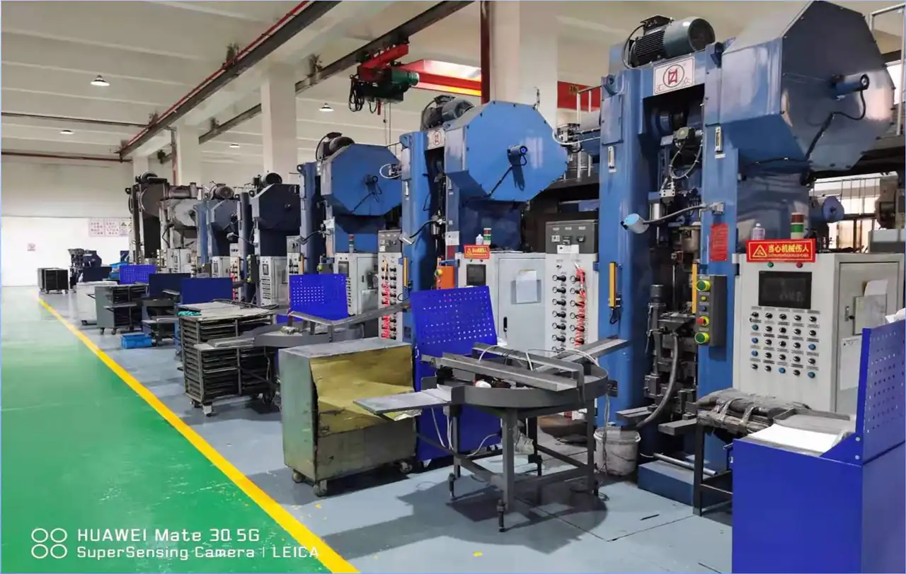
Secondary Processing Equipment
Comprehensive equipment lineup for all post-sintering operations.
CNC Equipment
- CNC machining centers
- Precision drilling machines
- Surface grinders
- Thread tapping machines
Sizing Presses
- 15T sizing press
- 40T sizing press
- 80T sizing press
- Automated sizing lines
Auxiliary Equipment
- Vibration grinding machines
- Sand blasting equipment
- Ultrasonic cleaners
- Vacuum oil impregnation
Machining Sintered Steel: What Actually Changes vs Bar Stock
Sintered steel machines differently from wrought bar stock, and nearly every difference traces back to porosity. Pores interrupt the cut at a microscopic scale, so chips break into short segments instead of forming continuous strings, and cutting edges wear by micro-chipping rather than steady flank wear. Heat behaves differently too: the porous matrix conducts heat away less readily, so heat removal at the cutting edge can be less effective than in wrought steel — particularly in deep drilling. The practical consequences are adjusted speeds and feeds, sharper and more positive tool geometries, and surface finishes capped by the exposed pore population rather than by feed rate alone.
Pores Are Built-In Chip Breakers
The same porosity that complicates tool life prevents the long, stringy chips that wrap around tools and fill bins in wrought machining. On automated cells this is an operational convenience — chips clear themselves. Operators machining sintered parts for the first time usually report the chip behavior before anything else.
Coolant Goes Where Chips Cannot
In parts with interconnected porosity, coolant and cutting fluid can penetrate the pore network. For parts that must be pressure-tight or plated afterward, the conventional sequence is to machine first and resin-impregnate before leak testing or plating. Oil-impregnated bearings are machined before oil filling whenever the schedule allows, because heavy cutting can heat trapped oil to the point of bleeding and smoking.
Tool Wear Changes Mode
Expect edge micro-chipping from interrupted pore contact rather than the gradual flank wear of continuous cutting in solid steel. Sharp edges, positive geometry, and coated tooling are the typical response; conservative parameters on the first cut into a sintered part save the tool budget.
Machinability Depends on the Sintered Grade
Free-graphite iron-carbon grades and copper-infiltrated parts are generally easier to machine than plain iron-carbon grades, with results depending on grade, density, and processing. Powder suppliers also offer machinability-additive grades — manganese sulfide is the classic example — developed specifically to extend tool life in sintered parts, worth specifying when a part carries heavy drilling or tapping content. Material selection is covered across our PM materials pages.
For the buying-side comparison — total cost, tolerances, and when PM beats machining from solid — see powder metallurgy vs machined bar stock.
Common Applications
Secondary machining operations for various PM part applications.
Gear Sizing
Achieving precise tooth profiles and bore dimensions
Bearing Bores
Precision machining of inner diameters for bearing fits
Thread Tapping
Adding threaded holes to sintered components
Surface Grinding
Achieving flatness for mating surfaces
Cost & Tolerance Decision Ladder
Tolerance in powder metallurgy is bought on a ladder, and every step up costs more per part. The discipline of economical PM design is buying each dimension at the lowest rung that satisfies the drawing — die-controlled where possible, sized where the geometry responds, machined only where sizing cannot reach, ground only on faces that demand it.
| Ladder Rung | Typical Tolerance Context | Relative Cost | Jump to This Rung When… |
|---|---|---|---|
| As-sintered (die-controlled) | IT8-9 typical; non-critical dimensions | Baseline | The drawing tolerances fit as-sintered capability |
| Sized / coined | IT6-7 typical on die-contacted features (bores, ODs, flat faces) | Small step above baseline | Precision fits on bores, ODs, or flatness — and the geometry responds to sizing |
| CNC machined | IT5-6 typical on machined features | Charged per machined feature | Cross-holes, threads, slots, or location tolerances the dies never touch |
| Ground | Tightest flatness and finish on selected faces | Highest per-feature cost | Sealing or gauge surfaces below the machining finish range |
Most cost overruns in PM programs trace to one mistake: applying machined-part tolerances to dimensions the die or sizing die already holds. The PM tolerance planning guide walks the tolerance budget feature by feature, and the DFM guide shows how to redesign features out of the top of the ladder entirely.
Related Resources
Use these internal links to keep moving through the most relevant guides, service pages, and technical references for this topic.
Powder Metallurgy Process
See where sizing, machining, and finishing fit into the full PM process route.
Surface Treatments
Compare machining with coating, impregnation, and heat-based finishing options for final performance.
PM Tolerance Planning Guide
Use this guide to decide when machining is necessary and when sizing or design changes are enough.
DFM Guide
Reduce unnecessary secondary work by designing PM parts around tooling and process capability from the start.
Frequently Asked Questions
Can you machine sintered parts the same way as wrought steel?
Yes, but parameters and expectations change. Porosity turns the cut into micro-interrupted cutting: chips break into short segments, cutting edges micro-chip rather than wear steadily, and heat removal at the cutting edge can be less effective than in wrought steel, particularly in deep drilling. In practice that means sharper, more positive tooling, conservative first cuts, and a surface finish ceiling set by the pore population. Parts that must be pressure-tight or plated afterward are typically resin-impregnated after machining.
What tolerance can secondary sizing achieve vs machining?
Sizing typically reaches the IT6-7 grade on the features the sizing die contacts — bores, outer diameters, and flat faces. Machining goes tighter, typically IT5-6 on machined features, and is the only route for transverse features and threads. Exact capability depends on part geometry and material; confirm critical dimensions for your drawing with our engineering team.
Which secondary operations are cheapest first?
Sizing and coining are the cheapest precision steps because they run at press-cycle speed. Drilling and tapping follow — necessary wherever threads and cross-holes exist, priced per feature. CNC machining is the next step up, and grinding sits at the top of the ladder on selected faces only. The economic rule of thumb: hold every dimension at the lowest rung that meets the drawing, and design parts so as few features as possible live at the top.